Project
Fixed-Wing 6-DOF Flight Dynamics & Robust Control Simulator
Nonlinear Flight Dynamics · Autonomous Control · State Estimation · Robustness
Built a nonlinear fixed-wing UAV simulation from the rigid-body equations upward, then designed PID and nonlinear dynamic-inversion flight controllers and tested them with realistic actuators, noisy sensors, EKF state estimation, wind and Dryden turbulence.
Closed-loop simulator
Each layer is a separate system, validated on its own, then closed into one loop. The controller only ever sees estimated state — never simulator truth — when the EKF is active.
Nonlinear rigid-body model
A full nonlinear rigid-body fixed-wing model in a 13-state quaternion representation, integrated with a fixed-step RK4 solver at 500 Hz (dt = 0.002 s).
- 3D position
- Body-frame velocity
- Quaternion attitude
- Body angular rates
- Translational motion
- Rotational motion
- Coriolis coupling
- Full inertia tensor
- Gyroscopic coupling
- Gravity transformation
- Quaternion kinematics
Forces and moments from air-relative flow
Aerodynamic forces and moments are computed from angle of attack, sideslip, body rates and control-surface deflections, using an Aerosonde coefficient set and a parabolic drag polar. Forces use air-relative velocity, so atmospheric wind actually changes the aerodynamics.
CD = CD0 + CL² / (π · e · AR)- Angle of Attack
- Sideslip
- Body Rates
- Aileron
- Elevator
- Rudder
- Lift
- Drag
- Side Force
- Roll Moment
- Pitch Moment
- Yaw Moment
Thrust acts through the CG. Propeller reaction torque, p-factor and propeller gyroscopic effects are intentionally omitted — not modelled and not claimed.
Numerical steady-flight trim
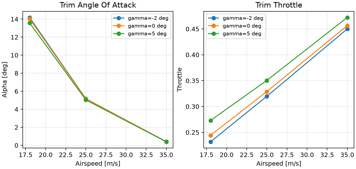
Given airspeed, altitude and flight-path angle, a numerical solver finds the angle of attack, elevator and throttle required for steady flight. Accepted trim residuals are below 1 × 10⁻¹⁰.
- 18 m/s
- 25 m/s
- 35 m/s
- −2°
- 0°
- +5°
Unreachable operating points are reported as unreachable rather than moving the benchmark to make the solver pass.
Linear model and flight modes
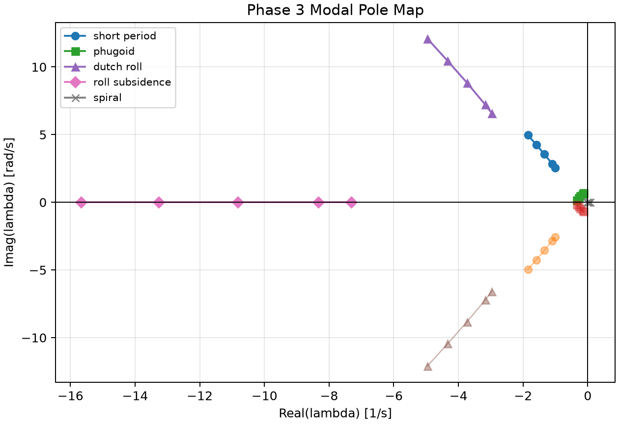
The nonlinear model is linearised around trim with central finite differences, then split into longitudinal and lateral-directional dynamics with automatic mode identification.
δẋ = A·δx + B·δu- Short Period
- Phugoid
- Dutch Roll
- Roll Subsidence
- Spiral Mode
- Eigenvalue
- Natural Frequency
- Damping Ratio
- Period
- Time to Half
Linear vs nonlinear
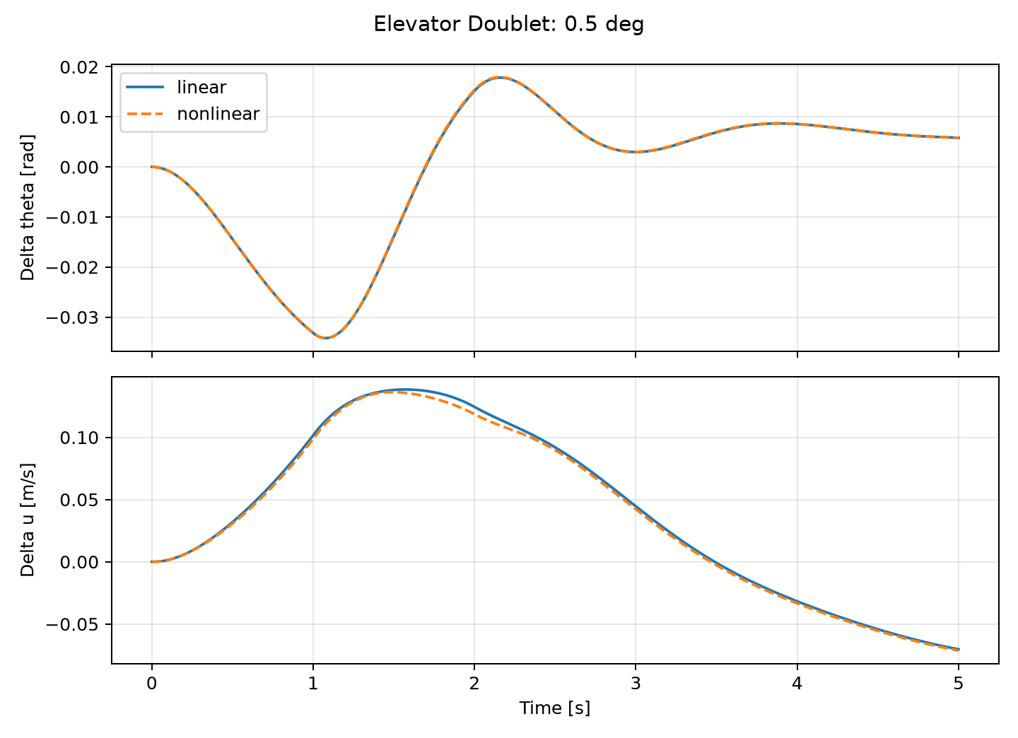
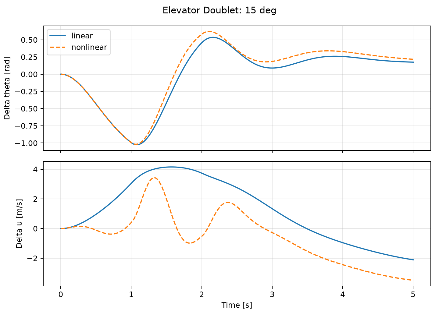
The linear model is checked against the full nonlinear simulator — matching for small perturbations and deliberately diverging for large ones. The point is to show the A/B matrices were validated, not assumed.
Cascaded PID architecture
Coupled altitude / airspeed control
The outer loop uses a simplified Total Energy Control System: throttle controls total energy while pitch controls how energy is distributed between altitude and airspeed, so the two work together rather than as independent loops. Heading changes add coordinated-turn yaw-rate feed-forward.
Ideal-model performance
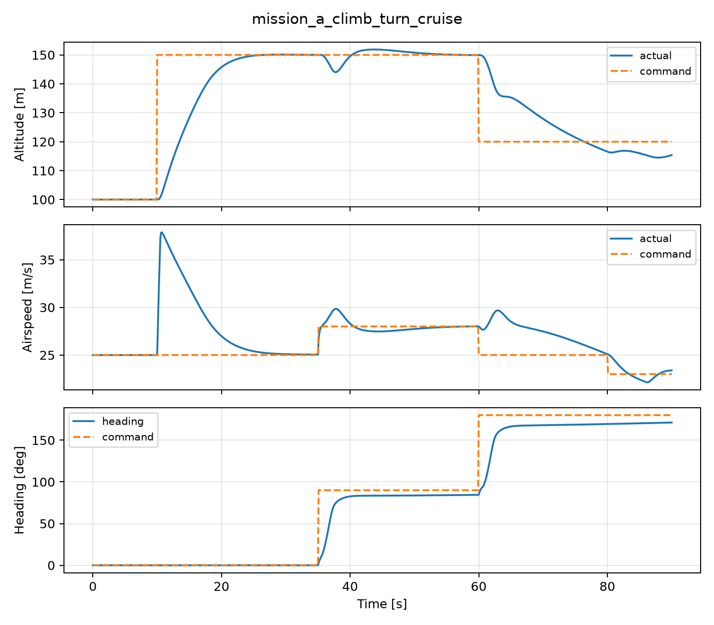
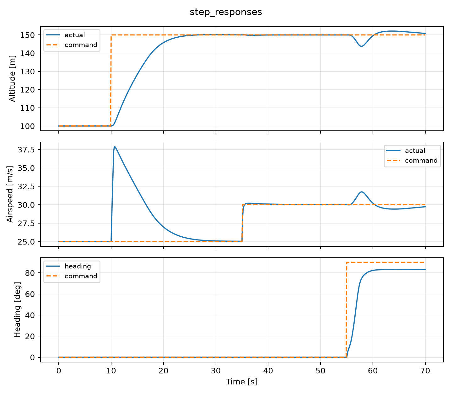
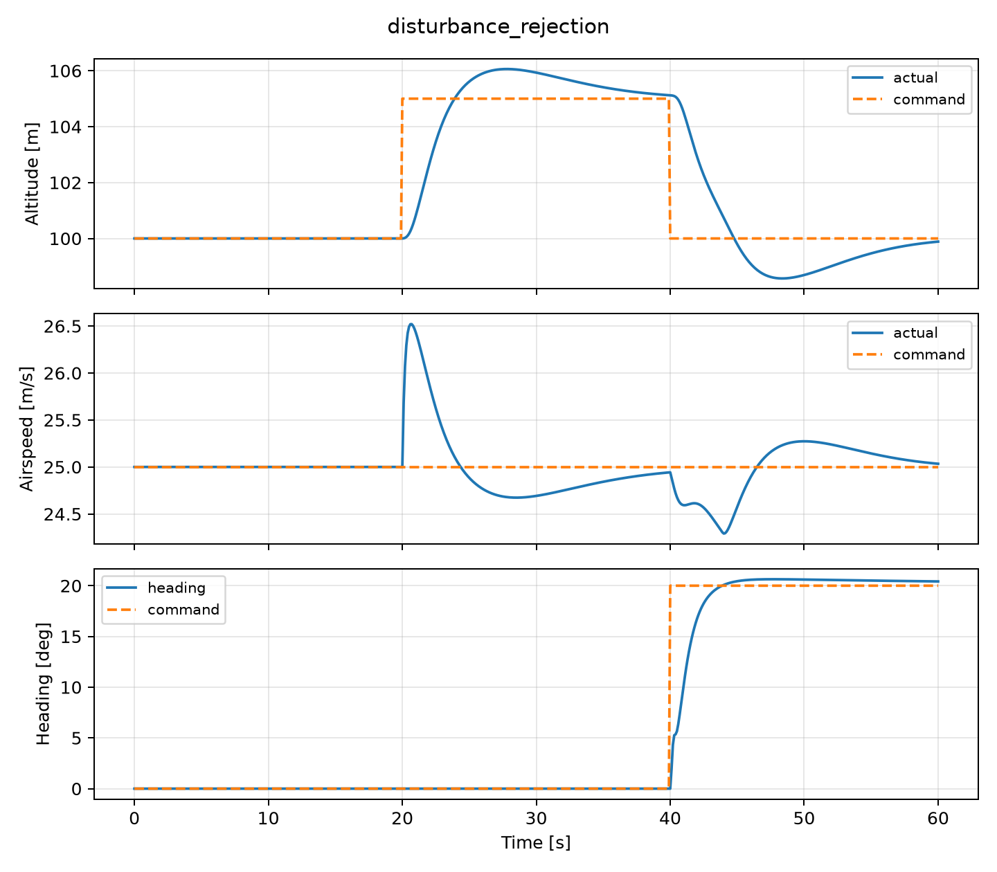
The baseline controller flies the committed ideal-model scenarios — Mission A (climb / turn / cruise), step responses and disturbance rejection — with no envelope violations and no surface saturation.
Replacing ideal assumptions
Surfaces do not move instantly
Simulated sensor suite
- Sampling Rate
- White Noise
- Random-Walk Bias
- Zero-Order Hold
- IMU — 200 Hz
- GPS — 5 Hz
- Pitot / Barometer / Magnetometer — 50 Hz
15-error-state navigation EKF
A 15-error-state navigation EKF tracks position, velocity, quaternion attitude and gyro / accelerometer biases, fusing IMU, GPS, barometer, pitot and magnetometer at their own rates.
- Position
- Velocity
- Quaternion Attitude
- Gyroscope Bias
- Accelerometer Bias
- Predict / Update
- Sensor Fusion
- Bias Estimation
- Joseph Covariance Update
- Multi-Rate Measurements
Accelerometer attitude corrections reject strongly dynamic specific-force measurements, so manoeuvre acceleration and turbulence are not mistaken for gravity.
Steady wind and Dryden turbulence
The environment adds steady wind with optional altitude shear, and Dryden turbulence via shaping filters at light / moderate / severe levels. The realistic benchmark uses 5 m/s steady wind at 45° with moderate Dryden turbulence.
Which realism actually hurts control?
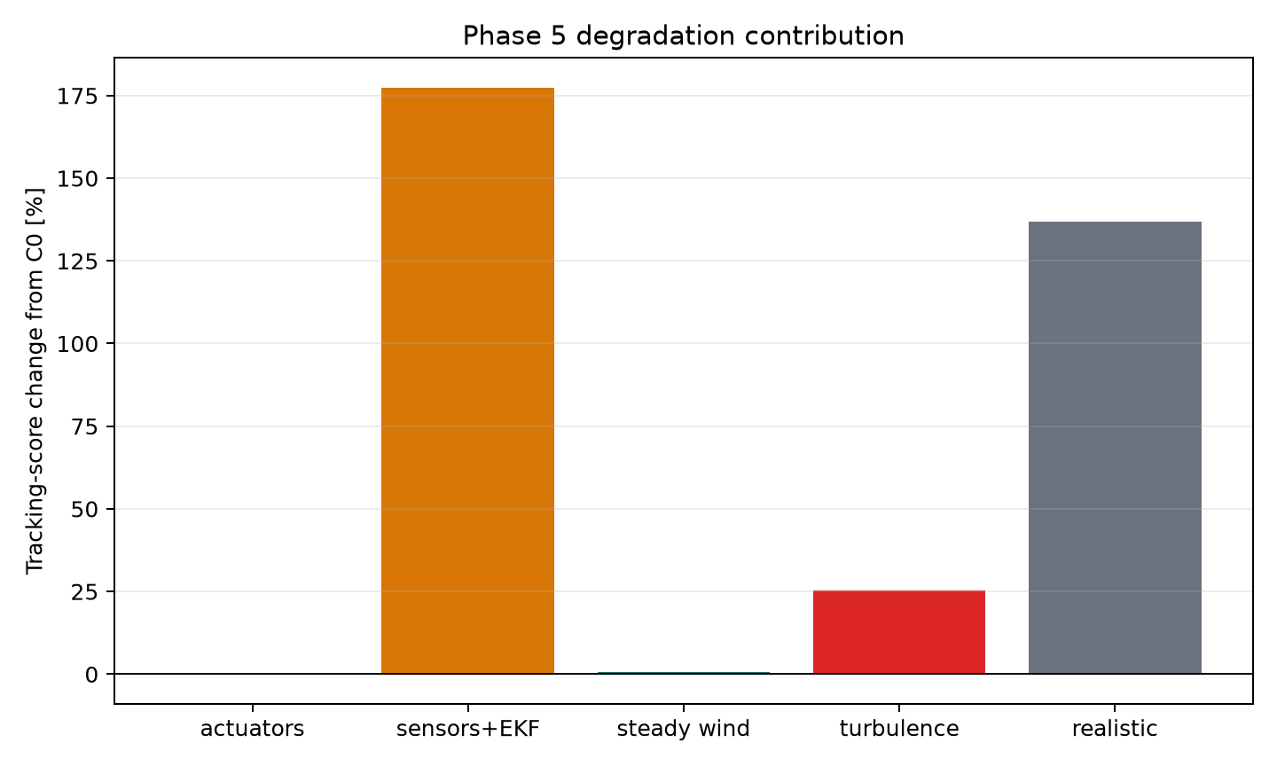
An ablation study isolates which realism mechanisms degrade tracking, scored by Altitude RMSE + 4 × Airspeed RMSE. Overall it rose from 16.008 → 37.937 between the perfect (C0) and fully realistic (C5) configurations.
The sensor / estimator chain produced the largest isolated degradation (+177.5%) — not the wind or actuator model.
A model-based rate controller
An alternative angular-rate controller using Nonlinear Dynamic Inversion. It computes the angular acceleration it wants, then approximately inverts the aircraft's angular dynamics for the required surface commands.
ω̇ = f(x, air) + g(air)·δ- f = uncontrolled angular dynamics
- g = control-surface effectiveness
- δ = aileron / elevator / rudder
Distributing demand across surfaces
NDI does not command each surface independently. Multivariable allocation redistributes the achievable demand across the free surfaces when one control reaches its limit.
Not naïve textbook inversion
The controller logs its numerical health so poor conditioning or allocation failure can be investigated after a run.
An engineering decision from testing
Full aerodynamic cancellation was too sensitive to estimated air-angle errors. The screened operational candidate used only partial cancellation blended with the baseline PID.
A negative result, kept
Hypothesis → implementation → fair test → result. In the sensor-aware screening test (lower is better):
The current NDI candidate did not beat the competent PID baseline strongly enough to pass the project gate. A separate provisional realistic 36-flight comparison gave NDI mean tracking 35.96 and PID 37.94 — but both achieved 0% success under the frozen strict mission criteria, and the repository marks this result as provisional.
NDI is not claimed to be superior. The negative result is reported as it stands.
Same conditions for both controllers
PID and NDI are compared under identical conditions; neither sees simulator truth while the EKF is active.
NDI sensitivity to model error
A resumable framework sweeps errors in the NDI internal aircraft model with paired PID comparisons.
The full large-mismatch campaign is not finished — the project deliberately blocks the expensive campaign until a nominal NDI pilot first outperforms PID.
Frozen benchmarks, recorded provenance
- Reference Frames
- Control Signs
- Aircraft Parameters
- Integration Settings
- Success Criteria
- Scenario Definitions
- Git Commit
- Config Hash
- Random Seed
- Controller Version
- Dirty / Clean Worktree State
Seeded random streams let stochastic comparisons be reproduced and controllers compared on identical disturbances.
Validation gates, not eyeballed plots
The project advances through validation gates rather than accepting “the plot looks right” as proof.
Planned next stages
Not yet implemented — future phases, not current results: